The Illovo Project
Introduction
When the Hunslet Engine Company took over the goodwill and drawings of the Avonside Engine Company of Bristol in 1934 they inherited the designs for geared steam locomotives. These consisted of a frame mounted on two four wheeled bogies powered by a steam engine of Vee configuration mounted under the boiler driving the wheel by shafts. Hunslet’s designs tended to be evolution and not revolution so it was natural for these novel designs to be perpetuated and developed.
With the advent of diesel power it was again natural for the format to be powered in this manner. Over the years a number of B-B and Bo-Bo designs have emerged starting with the diminutive eighteen inch gauge locomotives for the Woolwich arsenal to a variety of narrow and standard gauge types. Don Townsley’s book The Hunslet Engine Works has interesting examples on pages 113, 123, 198 and 213.
A number of two foot gauge types were built including two in 1955 and 1963 for the Illovo sugar works in Natal. These locomotives carried the Hunslet house style of bodywork prevalent at the time.
The design.
I have been unable to obtain a general arrangement for the locomotives so a design has been developed from available photos, known dimensions and drawings of standard gauge shunter’s fitted with similar bodies. The design has been tweaked to allow for suitability of use on my line and the use of commercial components. I have not slavishly copied all details but tried to capture the look and feel of the designs.
To start with – the chassis.
The bogies are standard components from Essel Engineering, part number 009A. In my eye’s they have a problem in that they are gauge convertible and therefore look wrong for two foot gauge and in addition they carry no detail.
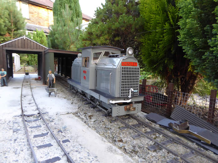
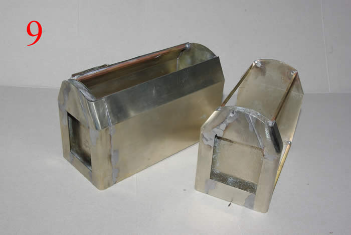
Photo 1 shows the bogies after the stretchers have been reduced, the frames are reversed to place the thrust surface of the bearing against the wheel instead of the fly crank. GRS tender axle boxes have been fixed to the frame then drilled and reamed.
Photo 2 shows the frame, the material is cold reduced Corten 3mm thick steel, a bit over the top but it was available, it’s strong and flat. The bolsters have been made from brass and fitted and the holes milled for the bogie motors to protrude through.
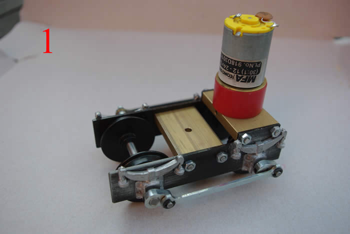
Photo 3 shows the modified bogies prior to painting. The buffer beams are fitted as are the inboard frames. These frames carry the dummy carden shafts. For these I used K&S brass tube for which I needed two tubes of consecutive sizes to telescope one inside another. The two sizes I had to hand are too large and will be replaced once I’ve been to the model shop. The motors have been fitted with terminal blocks to facilitate bogie removal without de-soldering.
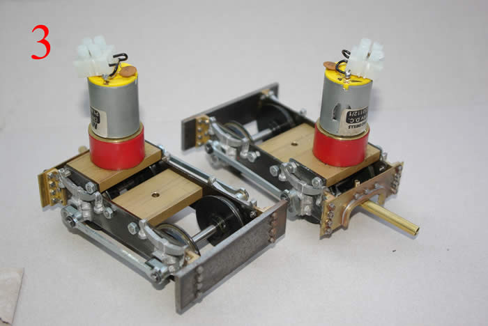
Photo 4 shows the scuttle fabrication and the two air receivers after priming. The scuttle one the prototypes houses the final drive to the two bogies. I have used the usable space to house a Mac 5 speed controller. The Mac 5 was removed from another project as I caused excessive motor chatter. However it has the beef to handle twin motors and in this installation runs smoothly. The scuttle is a straight forward steel and brass fabrication riveted and bolted together. The air receivers are 15mm copper pipe with end made from thin copper dished by a ball bearing over a hole in a piece of hardwood.
The electrics and controls.
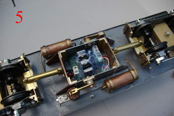
Photo 5 shows the assembled underside. The Mac 5 sits neatly in the scuttle and receives an air flow over the heatsinks. The two carden shafts are fitted with slotted holes to allow the bogies to pitch over track irregularities.
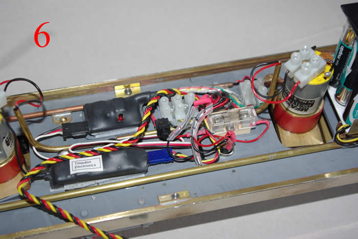
Photo 6 shows the top of the frame. I have used the Timpdon Electronics’ URX1 receiver and URC5 controller, these being mounted by sticky back Velcro pads which help to damp vibrations to the units. The Timpdon system gives as well as speed and directional control two other functions; one is used for lights switched by the reverser and one for horns. The URC5 is used to control a third party speed controller hence the use of the Mac 5. To provide enough volts to the Como motor 14.4 volts is used and is stored in two series connected battery packs mounted over the bolsters. This arrangement leaves a clear area in the centre of the frame where the cab sits so as a detailed interior can be provided. Horn buzzers are mounted on each battery pack and will sound through the radiator grilles on the body shell. The charger socket and on-off-charge switch are either side of the fuse holder and project under the frame between the scuttle sides. The black/yellow/red cable is the flying lead that will connect to the body shell and provide lighting. The black push button in the centre of the picture is used to lock the receiver to the transmitter – hopefully as this is now locked it is redundant! To keep wiring tidy where possible the wires are run in tube conduits screwed to the frame.
The Bodywork.
My liking of Hunslet diesel and steamers is the rugged workmanlike appearance of the finished machine, functionality produces form would be the design ethic. I wanted to encapsulate this functionality in the project and spent long time with drawings and cardboard mock-ups to get the correct feel of the design. For the body construction I decided to use nickel silver sheet as I personally find brass sheet a pain and I subsequently found nickel silver a joy to use. The prototype design has a heavy fabricated frame and foot plate with the bogies below and the bodywork above. As I have used a flat plate (photo 2) for the chassis frame structure of the model so the frame fabrication could be made non-structural. This has the advantage of making the bodywork easily detachable from the chassis frame for servicing and repairs. For the main body I used 028” nickel silver sheet. There are number of features which are essential to capture the character of the design these created a number of challenges, see below as to how these were overcome
Photo 7 shows the body consists of two identical shaped bonnets of differing length either side of an offset cab.
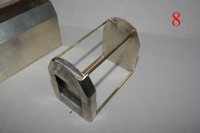
The first step was to make four identical plates shaped to the cross-sectional profile of the bonnet, (middle of photo). These would then be used to get the ends and sides into the correct position and ensure both bonnets were equal. The bonnet ends have a radius to the vertical edge with an inward taper to the top section of the bonnet. The edge was made from two strips folded around a ¼” dia rod. The mating edges of the two edges was sheared and filed to get a correct angle, (left hand side of photo) and then silver soldered for strength. Two pieces of ¼ sq brass box section were cut and laid horizontally across the profile plate at the top and bottom. The corners were soft soldered to this and an inverted V plate was soldered into the gap at the top and a rectangle at the bottom. This completed the bonnet fronts (right hand side of photo). Photo 8 and 9.
A bonnet front and a profile plate were then soldered with four square bars between them to give the overall bonnet length. The two sides were cut, folded and soldered to this as in photo 9. The top edges of the sides were then filed tapered prior to adding the top.
Photo 10. Shows the completed bonnets ready to have the detailing (louvres, handrails, grille and makers plates) fitted. The short bonnet is marked out for drilling bolt details, while the longer bonnet has the 1/32 rivets soldered on mimicking the bolts. These were spaced using Veroboard as a drill guide.
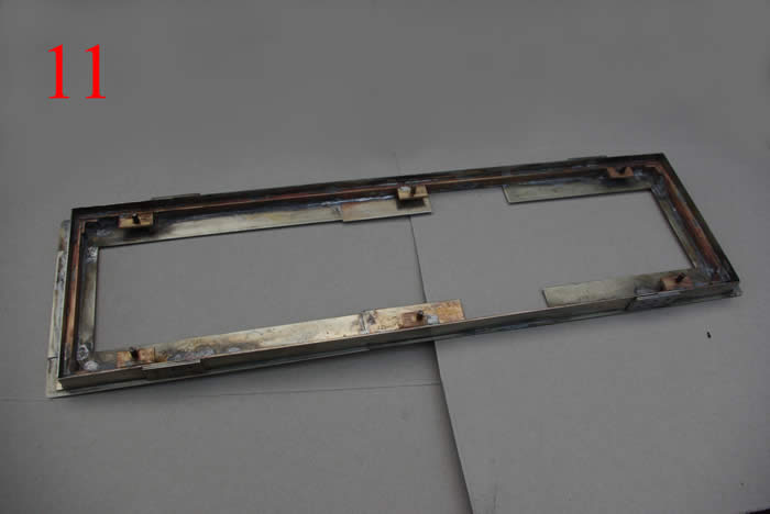
Photo 11 and 12. Shows the frame, this is made from K&S rectangular brass sections soldered into a rectangle marginally larger than the chassis frame. To the four sides of this are soldered nickel silver plates to represent the fabrication structure of the original. Six angle brackets were soldered to the insides of the rectangle then drilled and tapped 6BA and steel screws fitted. These push through holes in the chassis frame and are used to bolt the frame to the chassis. Once happy with the fit the footboards were sheared out and soldered to the top of the rectangle.
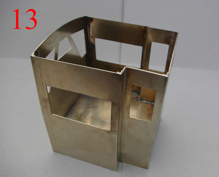
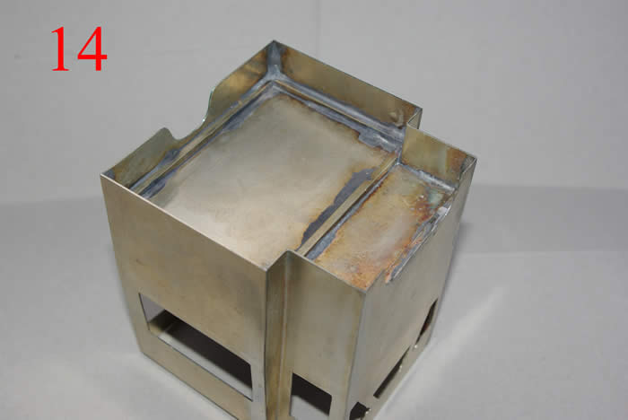
Photos 13 and 14. Show the cab, this is a straight forward lash-up from 0.028 thou nickel silver plate. The window apertures were cut out first and templates made to ensure they are symmetrical. The cab floor on the prototype is mounted higher than the footboard to clear the final drive unit. On the model I have lifted the floor a little higher, this helps give the cab rigidity. The sides of the floor are braced with square nickel silver bar and the cab internal corner braced with 3mm brass angle (the milled sort not the K&S folded sort).
Photos 15 and 16. Show the cab internal front and rear bulkhead overlays, as I didn’t have access to the actual controls so based them on contemporary locomotives. Hunslet early diesels required brute strength combined with skill and dexterity to change gear hence the levers were solidly engineered. The gear shift and throttle levers are connected and move. The controls are made from assorted brass sections, copper pipe, the air brake valve is filed from solid.
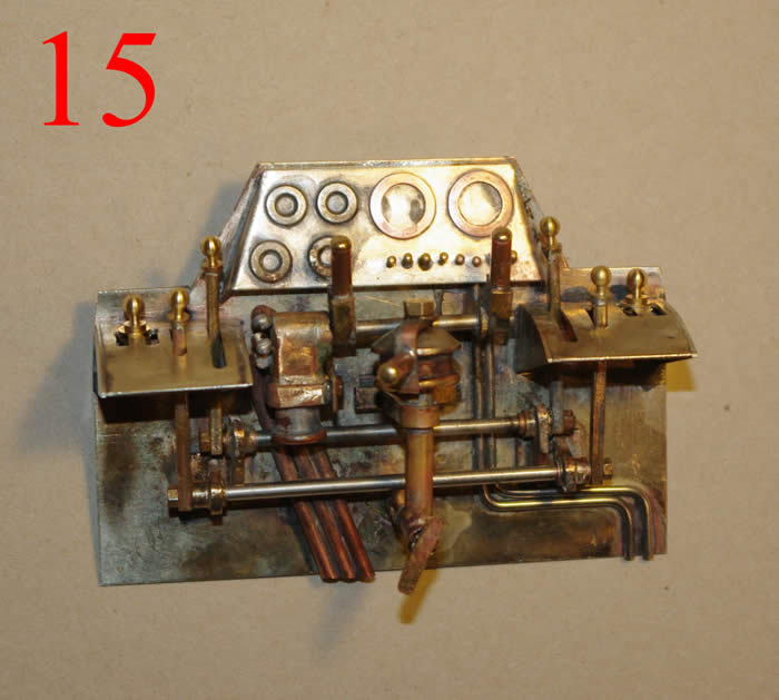
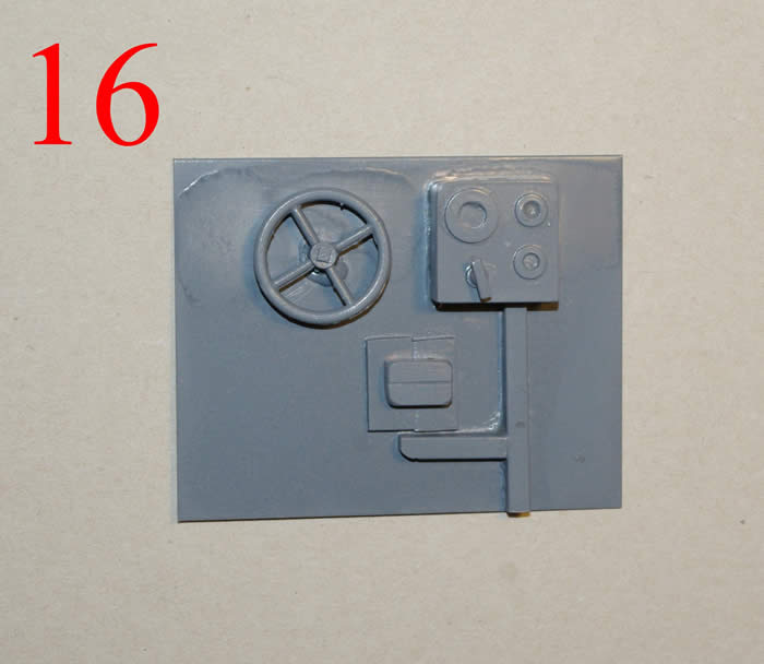
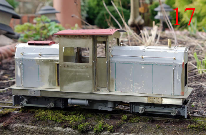
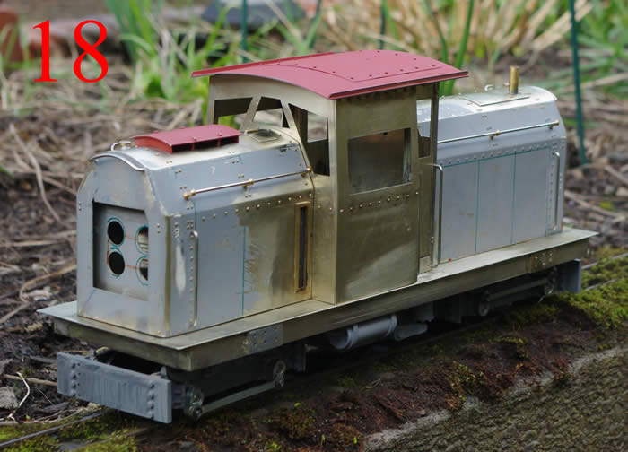
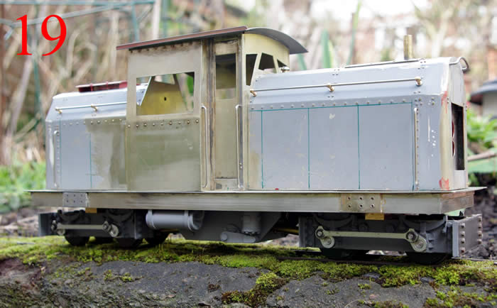
Photo 17, 18 and 19 show the first assembly of the bonnets and cab to the running board and fitted to the chassis. The piston cover mounted on the front bonnet (in red oxide) is insulated to the bonnet and acts as the beacon. The cab roof is a tight push fitted held in by the two air horn (not shown) which are soldered to bolts. as The green lines indicate where the side panels will mount, these are yet to be made as I still need to overcome the louvres issue. The cab window frames are yet to be fitted as is the bonnet front grille guards, other detailing needed are the cab steps, lifting brackets (mounted on the plates with six holes), coupling and vacuum pipes.
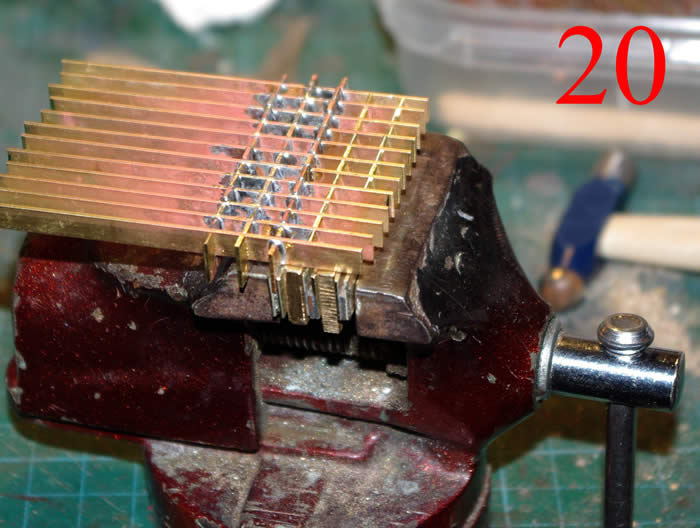
Someone once said decide what feature defines the prototype you are modelling and make this feature prominent on your model. The heavy grid-iron grilles used by Hunslet’s are certainly the defining feature of these locomotives. I struggled to find suitable materials and method to reproduce these but there was a stand at Peterborough selling heavy rectangular brass flats in long lengths. Quick eyeball measure of these satisfied me they would do the job and home they came. The plan was to use short lengths of the smaller flat; these would become the horizontal bars and soldered them to longer verticals of the bigger flat. In order to make the grille look convincing the accurate spacing and evenness would be paramount. The horizontals were duly cropped into 10mm lengths, these where inserted into a fixture made of a piece of the same thickness with two side cheeks. Three fixtures were made and spaced with two spacers.
Photo 20 shows the process, the fixtures are held in a vice and the horizontals are tapped into the fixture. Starting in the middle, between the horizontals the verticals are laid, with the first three rows it is imperative the verticals are parallel and level. Once happy the vice is removed from the bench and the end horizontals (these are sacrificial) clamped tight in a precision machine vice. This clamps the horizontals tight and as the material is a true rectangle with nice square and flat corners the assembly is held tight.
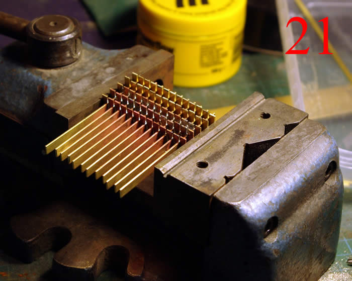
Photo 21 shows the assembly in the machine vice and soldered. Subsequent rows are added using one fixture in the last row soldered to maintain the spacing. The clamping action of the vice prevents any loss of the previously soldered horizontals when soldering subsequent rows. Once all the rows are added the protruding stubs of the horizontals are Dremelled off and the whole assembly was rubbed on a large flat second cut file to flattening all the bars level. Final finishing the grid was done with a square needle file and then final cleaning with a wire wheel in the Dremel.
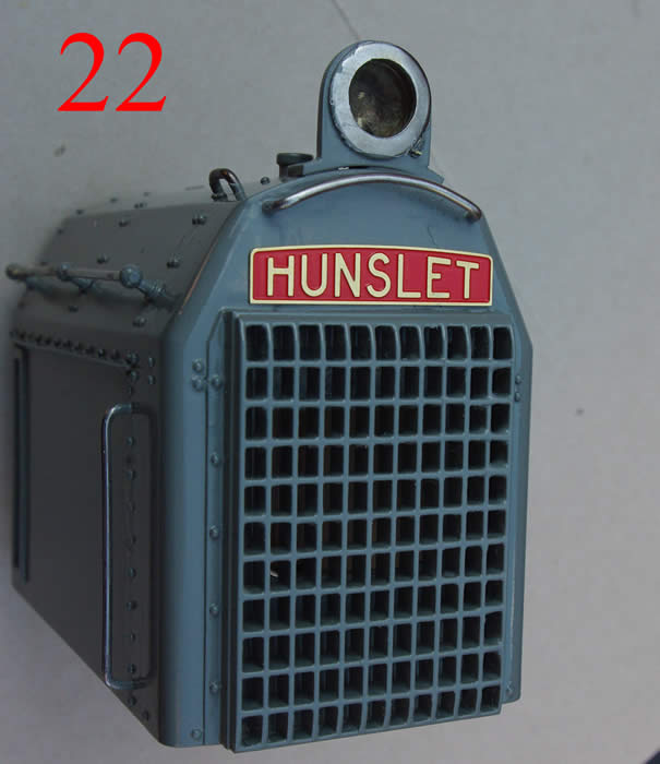
Photo 22 shows the end result fitted to the bonnet, this also shows the rather nice John Lythgoe Hunslet nameplates.